This sketch drive the display in order to show a number from 0 to 9 everytime a button connected to A0 is pressed.
Sidplay decoder how to#
Every time the button is pressed, the counter will be increased and the number's converted to binary! /*Įxample of how to drive a seven segment display using HCF4511 or similar
Sidplay decoder code#
From the above information, finally, we can conclude that this circuit can be changeable with timers as well as counters for displaying the CLK pulses, and also used as a timer circuit.As you can see the code is very simple. Thus, this is all about the BCD to 7 segment decoder display. This IC7447 gets the binary coded decimal like the input as well as gives the outputs like the related seven-segment code. The IC7447 IC is a BCD to seven segment decoder. BCD Seven Segment Display Using IC7447Ī decoder is one kind of combinational logic circuit that connects the binary data from n-input lines toward 2n output lines. Whereas in common anode, the familiar terminal for all the cathode terminal is of anode type. In common cathode, all the eight anode terminals use only a single cathode terminal, which is familiar. BCD Seven Segment Display Using IC 7447īasically, light emitting diodes are two types’ namely CC-common cathode as well as CA-common anode. Similarly, for all another grouping of the input switches, the same process would take place. Therefore the number ‘0’ will be exhibited.

Then the combinational logic circuit’s output will drive each and every one of output LEDs apart from ‘g’ to transmission. Once all the i/ps are connected to small logic. The operation of the above logic circuit can be understood with the help of truth table only. A combinational circuit can be built by using 4-inputs namely A, B, C, D and outputs on display like a, b, c, d, e, f, g. The final step of this is a designing of a logic circuit using the above k-map equations. From the above K-map simplification, we can get the output equations like these The simplification of k-map of the common cathode 7 segment decoder can be done in order to plan the combinational circuit. The third step in this design mainly involves designing the K-map (Karnaugh’s map) for every output expression as well as then shortening them to get inputs logic combination for every output.

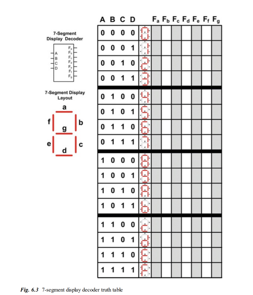
Thus ‘a’- segment is energetic for the digits like 0, 2, 3, 5, 6, 7, 8 & 9.īy using the above truth table, for every output function, the Boolean expression can be written.Ī = F1 (X, Y, Z, W) = ∑m (0, 2, 3, 5, 7, 8, 9)į = F6 (X, Y, Z, W) = ∑m (0, 4, 5, 6, 8, 9) For example, the column for a-segment illustrates the various arrangements for which it is to be light up. The truth table consists of seven o/p columns equivalent to each of the seven segments. The tabular form of a BCD to 7-segment decoder with a common cathode display is shown below. Already we have discussed above that is, for a common cathode display, the decoder output must be high in order to blink the segment. The designing of the truth table for the decoder mainly depends on the kind of display. The second step is the truth table design by listing the display input signals-7, equivalent four-digit binary numbers as well as decimal number. For instance, decimal number ‘1’ would control a blend of b & c. A truth table of this circuit can be designed by the inputs combinations for every decimal digit. This display can be constructed with seven LEDs in the form of H. The first step of this circuit design is an analysis of the common cathode seven segment display. The designing of BCD to seven segment display decoder circuit mainly involves four steps namely analysis, truth table design, K-map and designing a combinational logic circuit using logic gates. Design of BCD to 7 Segment Display Decoder Circuit A general cathode seven segment display includes 8 pins where 7-pins are input pins that are marked with from a to g & 8th-pin is a ground pin. The common terminals are either anode otherwise cathode. A seven segment LED display circuit can be built with eight LEDs. The circuit design, as well as operation, mainly depends on the concepts of Boolean algebraas well as logic gates.

The best examples of this circuit are multiplexers, demultiplexers, adders, subtractors, encoders, decoders, etc. The output of this circuit mainly lies in the current condition of the inputs. A combinational logic circuit can be built with logic gates which include inputs as well as outputs. It can be a BCD to seven segment decoder. A decoder is nothing but a combinational logic circuit mainly used for converting a BCD to an equivalent decimal number. The decoder is an essential component in BCD to seven segment decoder.

BCD to Seven Segment Display Decoder Theory


 0 kommentar(er)
